ELTAKO - Energiamittari 65A,1mod/18,B - FWZ14-65A Langaton,1-vaihe,DIN


Kirjaudu sisään tai luo tili tarkistaaksesi hinnan ja tehdäksesi tilauksen
Tärkeimmät tuotetiedot
Väyläjärjestelmä KNX - ei
Muut väyläjärjestelmät - ei ole
Malli / Tyyppi - energiamittari
Kytkentätapa - suora
Väyläjärjestelmä KNX radio - ei
Pakkaus ja ehdot
1 kpl
Vakiokäyttötuote
Tuotesarja
EAN-koodi
4010312501511
Sähkönumero
6712620
Toimittajan tuotenumero
FWZ14-65A
Tukkuerä
10
Väyläjärjestelmä KNX:
ei
Muut väyläjärjestelmät:
ei ole
Malli / Tyyppi:
energiamittari
Kytkentätapa:
suora
Väyläjärjestelmä KNX radio:
ei
Väyläjärjestelmä radiotaajuus:
kyllä
Väyläjärjestelmä LON:
ei
Väyläjärjestelmä Powernet:
ei
Kaksisuuntainen radiotaajuus:
ei
Hyväksytty PTB:n mukaan:
ei
S0 impulssiliityntä:
ei ole
Tariffikytkin:
ei
Tarkkuusluokka:
1
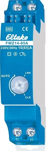
Langaton 1-vaihemittaus- ja lähetinmoduuli DIN-kiskoon, max. 65A, 1 moduuli 18mm leveä, tarkkuusluokka B, Arviointi tietokoneellavoidaan suorittaa GFVS-näyttö- ja ohjausohjelmistolla tai ener-giankulutusnäytöillä FEA55LED tai FEA55D.Syöksyvirta on 20mA.
Wireless single-phase energy meter transmitter module, maximum current 65 A
Connection to the Eltako-RS485 bus. Bus cross wiring and power supply with jumper.
The meter reading, the current power and the serial number will be handed over to the bus – eg for forwarding to an external computer, the software GFVS 3.0 or GFVS-Energy – and also to the wireless network via FAM14. For this it is necessary that a device address is assigned from the wireless antenna module FAM14, according to the manual.
To be displayed also with FEA55D and FEA55LED.
It measures active energy by means of the current between input and output. The internal power consumption of 0.5 watt active power is not metered.
1 phase conductor with a max. current up to 65 A can be connected.
The inrush current is 40 mA.
The meter reading, the current power and the serial number will be handed over to the bus – eg for forwarding to an external computer, the software GFVS 3.0 or GFVS Energy – and also to the wireless network via FAM14. To be displayed also with FEA55D and FEA55LED.Power consumption is indicated using a LED.
If the L input and the L output were interchanged when hooked up, a normal rate (HT)/off-peak (NT) switchover telegram is trans-mitted to indicate the hook-up error.
Wireless single-phase energy meter transmitter module, maximum current 65 A
- Only 0.5 watt standby loss.
- Modular device for DIN-EN 60715 TH35 rail mounting.
- 1 module = 18 mm wide, 58 mm deep.
- Accuracy class B (1%). With RS485 interface.
Connection to the Eltako-RS485 bus. Bus cross wiring and power supply with jumper.
The meter reading, the current power and the serial number will be handed over to the bus – eg for forwarding to an external computer, the software GFVS 3.0 or GFVS-Energy – and also to the wireless network via FAM14. For this it is necessary that a device address is assigned from the wireless antenna module FAM14, according to the manual.
To be displayed also with FEA55D and FEA55LED.
It measures active energy by means of the current between input and output. The internal power consumption of 0.5 watt active power is not metered.
1 phase conductor with a max. current up to 65 A can be connected.
The inrush current is 40 mA.
The meter reading, the current power and the serial number will be handed over to the bus – eg for forwarding to an external computer, the software GFVS 3.0 or GFVS Energy – and also to the wireless network via FAM14. To be displayed also with FEA55D and FEA55LED.Power consumption is indicated using a LED.
If the L input and the L output were interchanged when hooked up, a normal rate (HT)/off-peak (NT) switchover telegram is trans-mitted to indicate the hook-up error.